


Hydrogen Peroxide Dosing Tank
Category
零售价
市场价
重量
库存
隐藏域元素占位
- Overview
-
- Commodity name: Hydrogen Peroxide Dosing Tank
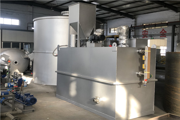
Characteristics of Hydrogen Peroxide Dosing Device Compact structure and good integrity: The device centrally installs dosing metering pumps, supporting pipelines and valves, pressure gauges, solution tanks, liquid level gauges, and corresponding electrical controls on the same frame base. It can be flexibly and conveniently combined into various chemical dosing treatment units for different purposes to complete the dissolution, preparation, and injection of chemical solutions. Multiple configurations available: It has various forms such as "two pumps with one tank", "three pumps with two tanks", "four pumps with two tanks", and "five pumps with two tanks". Equipped with metering pumps: The configured metering pumps have a flow range of 5–980 L/h and a pressure range of 1.0–26 MPa.
Product Introduction
The hydrogen peroxide dosing device is used for the treatment of feed water, boiler water, circulating water, and wastewater in power plants. It can also be applied in industries such as petroleum, chemical engineering, environmental protection, and water supply systems. As a unit-combined dosing device, its main components include a solution tank, a metering (1) [Note: The original text is incomplete here, and the specific metering component needs to be supplemented according to actual conditions], and an oilfield dosing device.
Characteristics of Hydrogen Peroxide Dosing Device
- Compact structure and good integrity: The device centrally installs dosing metering pumps, supporting pipelines and valves, pressure gauges, solution tanks, liquid level gauges, and corresponding electrical controls on the same frame base. It can be flexibly and conveniently combined into various chemical dosing treatment units for different purposes to complete the dissolution, preparation, and injection of chemical solutions.
- Multiple configurations available: It has various forms such as "two pumps with one tank", "three pumps with two tanks", "four pumps with two tanks", and "five pumps with two tanks".
- Equipped with metering pumps: The configured metering pumps have a flow range of 5–980 L/h and a pressure range of 1.0–26 MPa.
Brief Introduction to Hydrogen Peroxide Device
The dosing device and its supporting parts can be purchased and manufactured in accordance with national standards, as well as international standards such as API (American Petroleum Institute), ASME (American Society of Mechanical Engineers), SSPC (Steel Structures Painting Council), IEC (International Electrotechnical Commission), ASTM (American Society for Testing and Materials), and ANSI (American National Standards Institute). Appropriate materials, reasonable process flow design, advanced manufacturing technology, and strict quality control ensure the overall unit has excellent performance, making it suitable for conveying various strong corrosive media such as acids, alkalis, and salts.
Process Flow
The simple integrated dosing device mainly consists of a solution tank, an agitator, a metering pump, an electric control box, a water inlet valve, a sewage valve, internal installation cables, a device base, and a support platform. Solid or liquid chemicals are added into the chemical dissolving tank, then tap water is added in proportion for stirring and dissolving, and finally the solution is dosed to the dosing point by the metering pump.
The dosing control is generally manual, but it can also be automatic based on the control signal output by the upper-level system. The device is composed of a control system and a dosing system: the control system consists of an industrial pH meter, a regulator, a frequency converter, and a control circuit; the dosing system consists of a dosing pump and a chemical tank.
The dosing device is a chemical water treatment equipment for optimizing the circulating water system. Its principle is to control the dosage of chemical agents in the circulating water system through an online detection system and an automatic dosing system, effectively preventing scaling, corrosion, biological slime, and bacteria-algae problems in the circulating water system.
The control methods of the dosing device are mainly divided into manual control and automatic control. Automatic control can be further divided into multiple types such as time-liquid level control, pH control, conductivity control, online corrosion monitoring control, and online chemical concentration monitoring control. The selection of a suitable control method mainly depends on the user's on-site requirements. Different water bodies and different chemicals require different control methods. Therefore, when purchasing, you must clarify the design and technical requirements, otherwise, your efforts may be in vain.

Pre-Startup Inspection of the Dosing Device
- Check that all pipelines and valves are in normal working condition.
- Check that the metering pumps and agitators of all dosing equipment are in normal working condition.
- Check that the electrical equipment is in normal working condition.
The dosing device is composed of three main parts: 1. Electric agitator; 2. Solution tank; 3. Metering device, dosing equipment, and connecting pipes/valves.
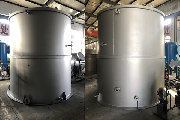
- Agitator: Composed of an agitator tank and an agitating device. Its function is to fully mix the solute (to be dosed) and water (solvent) after they are prepared in a certain proportion.
- Solution tank: Used to store the well-stirred solution for the dosing equipment.
- Metering device and dosing equipment: A metering pump is used for metering the solution to be dosed.
Description of Structural Characteristics of the Dosing Device
- Highly integrated integrated equipment.
- Small volume, simple operation, and convenient installation. On-site installation only requires connection to the water source and power supply.
- Safe and reliable operation with low maintenance workload.
- Good corrosion resistance: All parts in contact with the medium are made of engineering plastic materials.
Guide to Installing the Dosing Device
First, check whether the foot platform of the dosing device is on the same horizontal line (no anchor bolts are required). The pump's liquid outlet is equipped with threaded joints, quick connectors, and flange joints; connect the corresponding joints and then connect the power supply.
Complete the pre-operation preparations: Inject an appropriate amount of L-CKE460 worm gear oil and L-CKC460 industrial closed gear oil into the transmission box of the metering pump, with the oil level reaching the horizontal oil level line. Add the chemical solution manually or automatically, then connect the power supply and the electric control cabinet. If the power indicator light is on, it indicates that the power supply is connected. Press the button of the mixing tank to start the agitator; after it works for 3–5 minutes, open the pipeline valve and the flow control valve, then press the start button of the metering pump to start the metering pump.
For the dosing device, you should regularly check whether the feed port of the metering pump is blocked, and clean the pipelines and filters regularly to prevent blockage. In addition, check the agitating device regularly: see if the agitating shaft rotates flexibly, if the impeller is twisted or deformed, and if the coupling sleeve is loose. This is to avoid excessive shaft torque, increased stirring power consumption, and damage—if any damage is found, replace the parts in time.
In the dosing device, regularly inspect the safety valves, pressure gauges, and all pipeline valves to prevent leakage. When using a single pump or multiple pumps for dosing, alternate their use to avoid using or idling the same pump for a long time.
The dosing device is used in water treatment systems such as raw water, condensed water, boiler water, and demineralized water. By tracking changes in the water-steam quality of the thermal system, the dosing metering pump automatically adds chemical solutions to the water-steam system, maintaining the water-steam quality of the system in good condition and ensuring the safe operation of the unit.
During the natural operation of an industrial circulating cooling system, scaling or corrosion tendencies may occur due to the combined effects of factors such as the hardness, alkalinity, pH value, concentration multiple, temperature, and ambient humidity of the circulating water. Both scaling and corrosion have adverse effects on the safety and operation efficiency of the circulating cooling system. To inhibit scaling or corrosion, it is necessary to manually add buffers or scale inhibitors to the water. Common buffers and scale inhibitors include polyphosphates, zinc salts, polycarboxylates, etc.
The scale inhibitor dosing device mainly includes four parts: a chemical solution preparation system, a metering and dosing system, a safety system, and a control system. The addition of solid chemicals can be controlled in a follow-up manner and automatically added based on the control signal output by the upper-level system.
Initial Dosing Operation of Scale Inhibitor
- For the first dosing, clean the dosing tank first: Close the sewage valve at the bottom of the dosing tank during cleaning, inject water for cleaning, then open the sewage valve to drain the water. After cleaning twice, start adding the chemical.
- Adjust the dosing stroke of the metering pump: Turn the stroke adjustment knob of the metering pump counterclockwise to the corresponding scale.
- Prepare the chemical solution: Check and close the sewage valve at the bottom of the dosing tank. Calculate the amount of scale inhibitor to be added based on the effective volume of the dosing tank and the actual working capacity of the metering pump. Add the chemical from the inlet of the dosing tank, open the water inlet valve to dilute the solution to the liquid level scale, then close the water supply valve.
- Turn on the stirring motor of the dosing tank, stir the chemical solution evenly, then stop the motor.
- Open the inlet and outlet valves of the metering pump, turn on the metering pump switch, and dose the chemical before the security filter. After the RO (reverse osmosis) system is shut down, turn off the metering pump.
- Regularly inspect the dosing system for leakage and resolve any leakage promptly. Check whether the dosing amount of the metering pump is accurate, and verify if the drop in the liquid level of the dosing tank matches the calculated dosing amount of the metering pump. If there is a discrepancy, adjust the settings in a timely manner.
- Record monthly whether the total water inflow matches the dosing amount during the inspection cycle.
- When refilling the dosing tank, be careful not to exceed the liquid level.
- If the dosing tank is equipped with a low-liquid-level alarm, the central control PLC (Programmable Logic Controller) should be set to stop the dosing pump upon low-liquid-level alarm and switch to the backup dosing tank and metering pump for dosing. When preparing the scale inhibitor solution for the second time, calculate the volume of the dosing tank based on its actual capacity.
Evaluation of Chemical Use Effect
A simple method to evaluate the chemical effect is to measure the ratio of "Ca²⁺ concentration in concentrated water / Ca²⁺ concentration in influent water" to "Cl⁻ concentration in concentrated water / Cl⁻ concentration in influent water", denoted as K. A larger K value indicates better scale inhibition performance of the chemical. If K ≥ 99%, the chemical performance is considered excellent. For the detection methods of Ca²⁺ and Cl⁻ in water, refer to the national standards: GB/T 15452-95 and GB/T 15453-95. Meanwhile, the conductivity of the concentrated water can also be measured as reference data. Under the same operating conditions, when different chemicals are used, the higher the conductivity of the concentrated water, the better the scale inhibition performance.
Process Principle of Water Treatment Dosing Device
Natural water bodies contain a certain amount of colloidal particles. Under the action of electrostatic repulsion and Brownian thermal motion, these colloidal particles can overcome the influence of gravity, maintain a dynamic balance, and avoid agglomeration and precipitation—otherwise, the turbidity index of the water will be affected. A common method to remove colloidal particles is to add high-charge ions or polymer substances into the water. By using principles such as electrical neutralization, adsorption bridging, and net trapping, the colloidal particles are destabilized, agglomerated, and precipitated, thereby clarifying the water quality.
Common coagulants (coagulants aids) include aluminum salts, iron salts, and their corresponding polymers.
Overview of Water Treatment Dosing Device Process
This device mainly includes four parts: a chemical solution preparation system, a metering and dosing system, a safety system, and a control system.
Solid chemicals are added into the chemical dissolving tank, then industrial water is added in proportion for stirring and dissolving, and finally the solution is dosed to the dosing point by the metering and dosing system. The dosing control can be manual, or it can be follow-up controlled and automatically dosed based on the control signal output by a streaming current detector or the upper-level system.
The shortage of water resources worldwide has promoted the development of water treatment technology. Chemical dosing is a common technical measure in water treatment projects. However, in many water treatment projects, backward chemical dosing equipment leads to cumbersome manual operations, waste of high-value chemicals, and even affects the efficiency of enterprises.
In the process of feed water purification and wastewater treatment, it is necessary to add various chemicals (such as flocculants, coagulants aids, and defoamers for sewage) to achieve the treatment goal. Therefore, advanced dosing systems and chemical dissolving equipment are important components of water treatment projects.
Keywords:
Messages


Contact: +86 18016210178 (Ms.Liu)
Add:No.56, Donghuan Road, Zhucheng City, Weifang City, Shandong Province